Cognex Trevista CI Dome
The Cognex Trevista Dome is parameterized using the setup wizard. This takes over the correct configuration of all camera functions in the background.
Information: The correct setup and cabling can be found in the Cognex Trevista instructions.
Setting up the camera
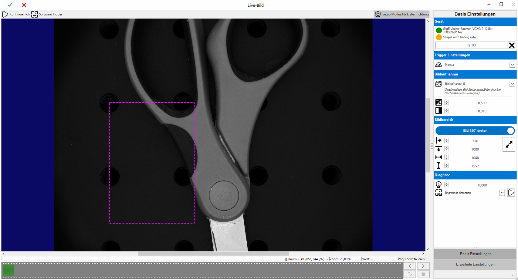
The camera settings are set automatically by the setup wizard and do not need to be entered in the program management. The setup wizard is started via the "Live image" button of the respective camera stationt.
Important: The wizard works universally for Trevista area scan and line scan cameras. The menu items are adapted specifically to the device.
Best Practise for the initial setup
It is recommended to set up the lens and the camera distance first
-
First start in "Setup mode for initial setup" mode
-
Start continuous image acquisition

-
Set a rough exposure time
 . 0.050 to 0.5ms is usually a good starting point
 -
Set contrast
 to 0 for optimum image quality
 -
Setting the working distance of the lighting
-
Focus the lens
-
Set trigger mode
Important: Make sure that the image in the area to be checked is not overexposed!
Once the camera has been mechanically set up, the detailed configuration is carried out
-
Only for area scan cameras:
-
Rotate image 180° according to the desired display
-
Parameterize additional image recordings
-
-
Define the area to be checked (ROI)
Main menu
The main menu contains control functions for setting up and testing the camera. The menu items are activated dynamically depending on the camera's operating mode.
| Menu | Description | |
|---|---|---|
|
|
Continuous | Starts continuous image acquisition by triggering one software trigger after the other. This creates the impression of a live image without overloading the system with too many images. |

|
Software Trigger | Triggers a single image acquisition. |

|
Setup Mode | This function is helpful for the initial setup of the system. It deactivates the ShapeFromShading image and provides a standardized greyscale image for setup. |
"Basic settings" menu
The basic settings are defined here.
|
|
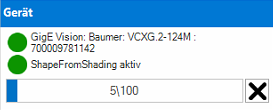
Device | ||

|
Camera |
Image capture device connected to the Trevista. Either GigE Vision camera or CameraLink frame grabber. |
|
|
|
ShapeFromShading |
Image capture mode: Setup mode or ShapeFromShading. |
|
|
Status display |
Image counter for diagnosing the acquired images. |
||
|
|
Trigger settings | ||

|
Mode |
The trigger mode is used to set the start signal for image capture: |
|
|
|
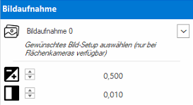
Image acquisition | ||

|
Image setup |
This option is only active for area scan cameras with active multi-image acquisition. |
|
|
|
Exposure time |
Exposure time of the image acquisition in milliseconds. |
|
|
|
Contrast |
Contrast level of the image: |
|
|
|
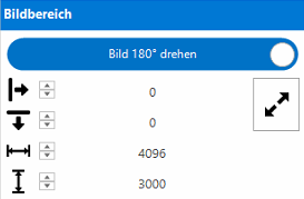
Region of interest | ||
|
Rotate image |
This option can be used to rotate the image of area scan cameras by 180°. |
||

|
Offset X |
Offset of the image area along the X-axis. |
|

|
Offset Y |
Only for area scan cameras: Offset of the image area along the Y-axis. |
|

|
Width |
Width of the image. |
|

|
Height |
Height of the picture. |
|

|
Maximize |
For area scan cameras: Maximizes width and height to the supported maximum of the camera. |
|
|
Information: The image area (dashed rectangle) can be set graphically in setup mode. |
|||
|
|
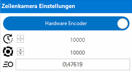
♣Line scan camera settings | ||
|
Line encoder |
This option is only available for line scan cameras: Software Encoder or Hardware Encoder |
||

|
Line frequency |
For software encoder: Line frequency in Hz. |
|

|
Lines/revolution |
For hardware encoders: Number of lines per encoder revolution. |
|

|
Speed |
For hardware encoders: Maximum line rate of the last recording to maximum possible line rate. |
|
|
|
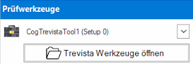
Inspection tools | ||
|
If setup mode is deactivated, the captured images can be loaded directly into the inspection tools from the sequence. Important: In multi-image mode, only the tools that are linked to the selected image capture are displayed. |
|||

|
Tools |
CogTrevistaTool or EasyTool (with CogTrevistaTool included) from the test sequence. All changes to the tool are written directly to the test sequence. |
|
|
|
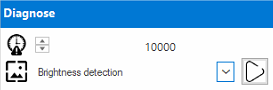
Diagnosis | ||
|
Important: The diagnostic functions are only available in setup mode! |
|||

|
Timeout |
Timeout for image capture in setup mode. |
|
|
|
Trevista Diagnose |
Diagnostics directly from the Trevista Grabber. These are used for the initial setup and testing of the device. The available diagnostics vary depending on the device type. |
|
"Advanced settings" menu
The advanced settings should only be changed by advanced users with the appropriate specific expertise.
|
|
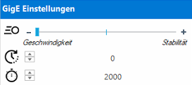
GigE settings | ||
|
|
Latency |
The latency level controls the CPU load during GigE transmission. |
|
|
|
Interpacket Delay |
Delay between sent packets (microseconds) to reduce the CPU load on the host PC. |
|

|
Request Timeout |
Specifies in milliseconds how long the GigE application should wait between receiving the header and trailer packets. |
|
|
|
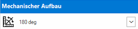
Mechanical design | ||

|
Alignment |
Mounting angle of the camera in relation to the CI Dome: |
|